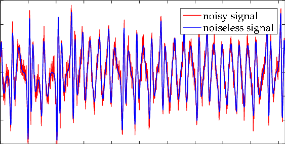
Electronic noise, too known as flag commotion or essentially noise, is an undesirable electrical flag that can meddled with the transmission and preparing of electronic signals. It is caused by irregular changes within the electrical signals that can result from a assortment of sources, counting warm clamor, obstructions from other electronic devices, and flag distortion.
The affect of electronic noise can shift depending on the sort of flag and the environment in which it is being transmitted or handled. In a few cases, noise can cause mistakes or twists in electronic signals, which can lead to decreased flag quality or indeed total flag misfortune. In other cases, noise may not essentially influence the execution of the electronic device or signal.
There are different strategies for lessening or killing electronic noise, counting the utilize of protecting to secure electronic devices from outside impedances, the utilize of noise-canceling methods to channel out unwanted noise, and the utilize of flag speakers to boost the quality of the flag and decrease the affect of noise. Furthermore, progressions in technology and advancements in electronic components have driven to the improvement of more modern clamor lessening methods that can offer assistance to move forward the generally execution and unwavering quality of electronic devices.
Types of electrical noise
There are a few sorts of electrical noise that can influence electronic signals, including:
Thermal noise: This sort of noise is caused by the irregular warm movement of electrons in a conductor. It is show in all electronic components and circuits and increments with temperature.
Shot noise: This sort of noise is caused by the irregular entry of electrons at a finder or intensifier. It is frequently display in gadgets that work at moo streams or with high-speed signals.
Flicker noise: Too known as 1/f noise, this sort of noise increments in adequacy as the recurrence of the flag diminishes. It is frequently show in low-frequency electronic components, such as resistors and capacitors.
Intermodulation noise: This sort of noise is caused by the blending of two or more signals in a non-linear device. It can result in undesirable flag twisting or interference.
Crosstalk: This sort of noise is caused by undesirable flag coupling between two or more conductors in near nearness. It can result in flag mutilation or impedances between the coupled conductors.
Electromagnetic interference (EMI): This sort of noise is caused by outside sources of electromagnetic radiation, such as radio waves, microwaves, and other electronic devices. It can result in flag twisting or impedances and is regularly decreased through protecting or sifting techniques.
Ground circle noise: This sort of noise is caused by contrasts in ground potential between two or more components in a circuit. It can result in undesirable flag obstructions and is regularly diminished through establishing or segregation techniques.
Understanding the sort of noise influencing an electronic flag is critical in creating successful commotion lessening procedures and guaranteeing dependable flag transmission and processing.
External Source of electrical noise
External sources of electrical noise are sources of obstructions that start from exterior of the electronic framework. A few common outside sources of electrical noise include:
Power lines: Control lines can create electromagnetic areas that can meddled with adjacent electronic devices.
Radio frequency (RF) radiation: RF radiation from sources such as radio transmitters, cell phones, and other remote devices can cause impedances with electronic signals.
Lightning: Lightning strikes can make high-frequency electromagnetic beats that can cause impedances with electronic devices.
Electromagnetic impedances (EMI) from other electronic devices: Other electronic devices, such as computers, printers, and fluorescent lights, can produce electromagnetic obstructions that can influence adjacent electronic devices.
Motors and other mechanical gear: Engines and other mechanical gear can create electrical commotion that can meddled with adjacent electronic devices.
Environmental variables: Natural variables such as temperature, mugginess, and barometrical weight can influence the execution of electronic components and make undesirable noise.
To diminish the affect of outside sources of electrical commotion, different procedures can be utilized, such as protecting to secure electronic devices from outside impedances, sifting to evacuate undesirable noise from signals, and establishing or separating electronic devices to avoid the stream of undesirable electrical current.
Internal Source of electrical noise
Internal sources of electrical noise are sources of obstructions that begin from inside the electronic framework. A few common inner sources of electrical noise include:
Active electronic components: Dynamic electronic components such as transistors and enhancers can producecommotion due to the irregular movement of electrons inside the component.
Passive electronic components: Inactive electronic components such as resistors, capacitors, and inductors can create noise due to their physical properties, such as warm commotion and flash noise.
Clock signals: Clock signals utilized in advanced circuits can produce noise due to their quick rise and drop times, which can cause undesirable flag reflections and crosstalk.
Power supply noise: Control supply noise can be caused by variances within the voltage and current provided to electronic components and can result in undesirable flag mutilation and interference.
Ground noise: Ground commotion can be caused by variances within the ground potential of electronic components and can result in undesirable flag interference.
Electromagnetic impedances (EMI) from inside components: Inner components such as engines, transfers, and transformers can create electromagnetic impedances that can influence adjacent electronic components.
To decrease the affect of inner sources of electrical noise, different methods can be utilized, such as appropriate circuit plan and format, the utilize of high-quality components, and the execution of noise diminishment methods such as sifting, protecting, and establishing.

Common Mode Noise
Common mode noise refers to electrical noise that shows up on both the “hot” and “neutral” wires in an electrical circuit, relative to ground. This sort of noise can be caused by a variety of sources, counting control supply changes, radio frequency interference (RFI), electromagnetic impedances (EMI), and ground loops.
Common mode noise can cause a number of issues in electronic frameworks, counting corruption of flag quality, expanded mistake rates, and indeed equipment harm or disappointment. To moderate common mode noise, originators frequently utilize strategies such as establishing, protecting, and sifting to diminish the affect of the noise on touchy circuitry. Furthermore, specialized components such as common mode chokes or baluns may be utilized to effectively stifle common mode noise in a circuit.
Normal Mode Noise
Normal mode noise, too known as differential mode noise, alludes to electrical noise that shows up on as it were one of the “hot” or “impartial” wires in an electrical circuit, relative to ground. This sort of noise can be caused by a assortment of sources, counting control supply vacillations, exchanging noise, and crosstalk between adjoining wires.
Normal mode noise can moreover cause a number of issues in electronic frameworks, counting degradation of flag quality, expanded mistake rates, and gear harm or disappointment. In any case, not at all like common mode noise, ordinary mode noise can regularly be more effectively tended to with detached sifting methods such as ferrite beads, capacitors, and inductors.
It’s worth noticing that both ordinary mode and common mode noise can happen at the same time in a circuit, and a combination of sifting strategies may be required to completely relieve the impacts of both types of noise.
Atmospheric Noise
Atmospheric noise, too known as normal radio noise, alludes to the electromagnetic radiation that’s created by natural wonders within the Earth’s climate. This sort of clamor is by and large broadband, meaning it covers a wide run of frequencies, and is caused by a assortment of sources, counting lightning, sun powered radiation, and infinite rays.
Lightning releases are the essential source of climatic commotion, creating a broad range of radio frequencies from many kHz to a few MHz. The radiation from these releases voyages along the Earth’s surface and through the air, and can be gotten by recieving wires as noise. Sun oriented radiation and enormous beams too contribute to air noise, in spite of the fact that their contribution is for the most part less critical than lightning discharges.
Atmospheric noise can be a noteworthy challenge for radio communication frameworks, especially those working at moo frequencies, such as AM radio. In any case, a few radio astronomers too utilize atmospheric noise as a source of data around the structure of the Earth’s climate and the behavior of lightning releases.
Shot Noise
Shot noise may be a sort of irregular electrical noise that arises from the discrete nature of electrical charge. It is caused by the irregular entry of individual electrons or gaps, which makes fluctuations within the current stream. Shot noise could be a principal clamor source in electronic devices such as photodiodes, transistors, and vacuum tubes.
Shot noise is characterized by a current that varies around a mean esteem with a standard deviation that’s relative to the square root of the normal current. The noise control range of shot noise is corresponding to the square of the recurrence and is free of temperature.
In electronic devices, shot noise can restrain the exactness and precision of estimations, and can moreover influence the execution of circuits. In a few cases, it can indeed be a restricting calculate within the affectability of a device. To mitigate the impacts of shot noise, architects can use techniques such as expanding the number of charge carriers or diminishing the current stream to play down its impact.
Transit Time Noise
Transit time noise could be a sort of noise that emerges in electronic devices such as diodes, transistors, and vacuum tubes due to the finite time it takes for electrons to travel through the device. When an electron enters the device, it encounters a random scattering prepare that causes it to veer off from its beginning direction, driving to a random variation within the time it takes for the electron to travel through the device.
This variety in travel time leads to vacillations within the current stream through the device, which can result in commotion. Travel time noise could be a shape of arbitrary clamor that contains a Gaussian plentifulness dissemination and a clamor power spectrum that increments with frequency.
Transit time noise can be a noteworthy challenge in high-frequency circuits, where the travel time of electrons gets to be a significant fraction of the period of the input flag. To moderate the impacts of transit time noise, originators can utilize methods such as lessening the device estimate, expanding the doping thickness, or utilizing extraordinary development procedures to play down the travel time of electrons through the device. Moreover, the utilize of feedback strategies and noise diminishment circuits can too offer assistance to play down the affect of travel time noise.
Transistor Warm Noise:
Transistor thermal noise could be a sort of arbitrary noise that emerges from the warm disturbance of charge carriers (electrons and gaps) in a transistor. The noise is caused by the irregular development of charge carriers due to warm vitality, which comes about in irregular varieties within the transistor’s yield voltage or current.
Transistor warm noise is regularly characterized by a Gaussian adequacy dispersion and a clamor control range that’s relative to the device temperature and the transmission capacity. The noise control range is level over a wide extend of frequencies, which makes it troublesome to channel out.
In electronic circuits, transistor warm noise can restrain the affectability and precision of estimations and can too influence the execution of speakers, oscillators, and other electronic devices. To play down the impacts of transistor warm noise, architects canutilize strategies such as increasing the transistor measure, diminishing the device temperature, or utilizing lower-noise transistors. In expansion, circuit methods such as sifting and noise diminishment can too offer assistance to moderate the affect of transistor thermal noise.
Signal to Noise Ratio:
Signal to Noise Ratio (SNR) could be a degree of the quality of a flag relative to the level of foundation noise.
SNR is commonly utilized in communication systems and flag preparing to quantify the quality of a flag. A better SNR demonstrates a more grounded flag relative to the noise, which for the most part leads to way better execution and more noteworthy unwavering quality of the system.
SNR = 10 * log10 (Ps/Pn)
For case, if a flag contains a control of 10 watts and the noise includes a control of 0.1 watts, the SNR can be calculated as:
SNR = 10 * log10 (10/0.1) = 20 dB
In this case, the flag is 20 dB stronger than the noise.
SNR can moreover be communicated in terms of voltage or current, by utilizing the formula:
SNR = 20 * log10 (Vs/Vn)
where Vs is the voltage or current of the flag and Vn is the voltage or current of the noise.
Electronics Noise Figure
Electronic noise figure (NF) could be a degree of the signal-to-noise proportion (SNR) corruption caused by clamor presented by electronic components within the signal chain.
It could be a way of quantifying how much noise is included to a flag as it passes through a device or system.
The noise figure is communicated in decibels (dB) and is characterized as the proportion of the entire noise control at the yield of a device or framework to the clamor control that would be show at the yield in case the device or framework did not contribute any noise.
Mathematically, the noise figure can be expressed as:
NF = 10 * log10 (Add up to yield noise control / Input noise power) where Add up to yield noise control is the control of the noise at the yield of the device or framework, and Input noise power is the control of the noise that would be show at the yield in the event that the device or framework did not contribute any noise.


